
Choosing Cnc Cutting Tools for global production is not a simple catalog decision. Buyers must connect tool geometry, workpiece material, machine power, spindle speed, and production volume. A sharp carbide end mill may perform beautifully on aluminum, yet fail quickly in hardened steel. Small details matter, including tool runout, coolant delivery, holder balance, and coating suitability.
Tony Schmitz, a respected machining researcher, explains the practical goal clearly: “The objective is to maximize material removal while maintaining acceptable part quality.” This principle should guide every international purchase. The lowest unit price can become expensive when tools create burrs, vibration, poor surface finish, or unexpected machine downtime. Ask suppliers for cutting data, inspection records, material compatibility, and repeatability evidence. Verify the recommendations through a controlled test cut.
Look closely.
A reliable supplier should explain why a tool fits your operation, not merely promote its hardness or coating. Global buyers also need consistent dimensions, secure packaging, traceable batches, and responsive technical support. Regional standards and machine configurations can change the result. Even experienced engineers sometimes select tools by habit, and that habit deserves review. The correct choice may involve a slightly higher purchase price, but it should reduce tool changes and rejected parts. This guide explores the factors that make Cnc Cutting Tools dependable across different factories, materials, and production conditions. Expect practical comparisons, measurable criteria, and a few uncomfortable questions about assumptions that often go untested.
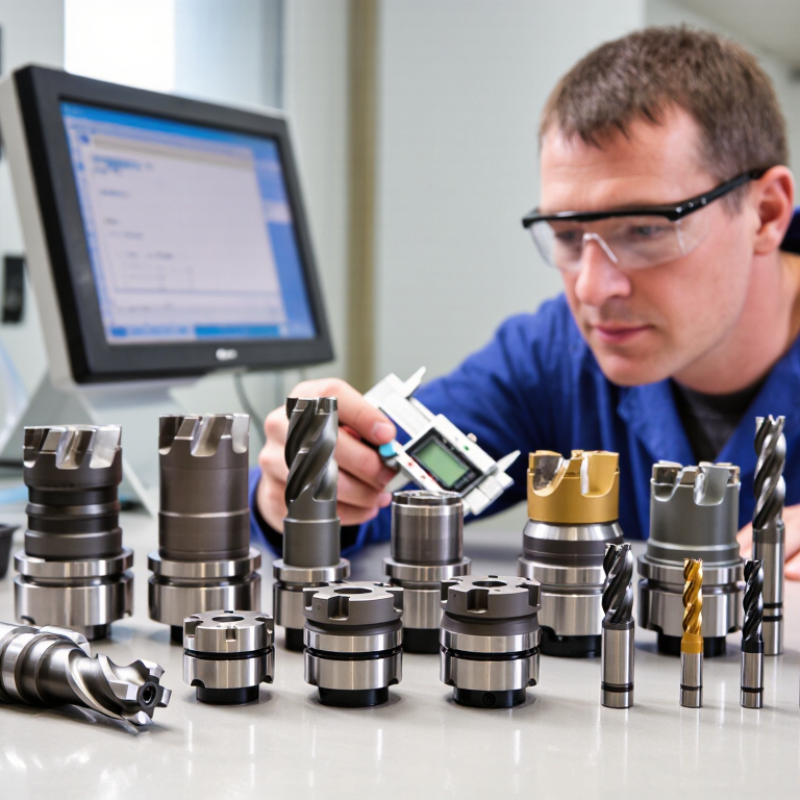
CNC cutting tools are defined by the work they perform. End mills create slots, pockets, contours, and narrow shoulders. Face mills remove material across broad, flat surfaces. Drills produce starting holes, while reamers improve the size and finish of existing holes. Boring tools enlarge holes with controlled accuracy. On a CNC lathe, turning tools and replaceable inserts remove material from rotating workpieces. Each type has a different machining role.
Start with the cut. For aluminum, a sharp, polished flute often improves chip removal. Tough stainless steel may need stronger edges, controlled cutting speeds, and steady coolant. Hardened steel demands heat-resistant tool materials and careful engagement. The machine also matters. A long tool holder can reach a deep pocket, but it may vibrate like a thin ruler. Shorter setups usually provide better rigidity and surface quality.
I have seen buyers choose tools by price alone. That decision can become expensive after chatter, broken edges, and rejected parts. Tool diameter, flute count, shank size, coating, and corner radius should match the machine and workpiece. Small details matter. Check technical drawings, tolerance data, cutting recommendations, and material certificates before ordering internationally. A sample test is useful, although one successful trial does not prove long-term performance. Review chip shape, spindle load, tool wear, and finished dimensions after several cycles.
Choosing CNC cutting tools begins with the workpiece, not the catalog price. Hardness, abrasiveness, toughness, and thermal conductivity control tool performance. For common steels below 45 HRC, cemented carbide offers a practical balance of wear resistance and toughness. Hardened steel may require ceramic or cubic boron nitride tools, especially during stable, continuous cutting. However, ceramic tools dislike shock. Interrupted cuts can cause sudden edge failure.
Aluminum needs sharp, polished edges and generous chip space. A diamond-coated or polycrystalline diamond tool can reduce built-up edge on abrasive aluminum alloys. It is usually unsuitable for high-temperature ferrous cutting.
Titanium transfers little heat away from the cutting zone. Sharp carbide geometry, moderate cutting speed, and careful coolant delivery are safer choices. Keep the edge keen.
Composite materials create another problem. Glass fibers can wear an edge quickly, so abrasion-resistant tool materials deserve attention. Yet excessive hardness may reduce toughness. I have seen operators choose the hardest tool and lose it during vibration. That choice was technically impressive, but operationally poor. Check machine rigidity, tool overhang, coolant compatibility, and spindle runout before final selection. A small runout error can erase the benefit of an expensive tool material. Trial cuts should record flank wear, surface finish, cutting sound, and chip shape. Some recommendations remain uncertain until real production data appears.
How to Choose CNC Cutting Tools for Global Buyers?
Selecting Tool Geometry for Cutting Accuracy and Efficiency
Choosing CNC cutting tools requires more than checking diameter and material compatibility. Tool geometry often determines cutting accuracy, chip control, and tool life. Rake angle, clearance angle, helix angle, flute count, and edge preparation deserve careful attention.
A high-helix tool can remove aluminum chips smoothly and reduce cutting resistance. For stainless steel, a stronger edge and moderate helix may handle heat more reliably. Fewer flutes create extra chip space during deep aluminum pockets. More flutes can improve feed rates when the machine and workholding remain rigid. Small details matter.
A 6 mm end mill with excessive clearance may cut freely but lose edge support. Too little clearance can increase rubbing, heat, and surface discoloration. I have seen a seemingly efficient geometry produce burrs after only a short production run. The cause was not always the tool; unstable clamping and incorrect feed settings also played roles.
Cutting tests should include spindle load, sound, chip shape, wall finish, and measured burr height. A clean finish is useful evidence, but it does not prove long tool life. Test the same geometry across the target material, depth, coolant method, and machine stiffness. Global buyers should request dimensional data and application guidance from qualified suppliers. Geometry charts can help, yet real results may differ between machines. This is where careful trial work prevents expensive assumptions.
Practical geometry guidelines for selecting milling and turning tools according to workpiece material, cutting conditions, accuracy requirements, and production goals.
| Tool Geometry or Tool Type | Typical Geometry Range | Best-Suited Materials | Primary Cutting Benefit | Accuracy and Surface-Finish Impact | Efficiency Considerations | Selection Cautions |
|---|---|---|---|---|---|---|
| Positive-Rake Milling Cutter | Positive radial rake; commonly about +5° to +15° | Aluminum alloys, copper alloys, plastics, and other ductile materials | Reduces cutting resistance and helps prevent built-up edge | Supports cleaner edges and lower burr formation when the tool is sharp and properly balanced | Efficient for high spindle speeds and high material-removal rates on machines with suitable power and rigidity | A very large positive rake can weaken the cutting edge and increase vibration in unstable setups |
| Neutral or Slightly Positive-Rake Cutter | Approximately 0° to +8° rake | General-purpose machining of low-carbon steel, stainless steel, cast iron, and non-ferrous metals | Balances edge strength with moderate cutting forces | Provides predictable dimensional control across a broad range of cutting conditions | Suitable for general production where one tool geometry must handle varied materials | May not provide the lowest cutting forces for soft materials or the strongest edge for interrupted heavy cuts |
| Negative-Rake or Strong-Edge Cutter | Approximately -5° to -15° rake, depending on insert and operation | Hardened steels, cast iron, nickel-based alloys, and interrupted cuts | Creates a stronger wedge-shaped cutting edge with improved impact resistance | Can maintain edge stability during demanding cuts, but may generate more heat and cutting force | Useful for rigid machines, heavy roughing, and operations requiring high edge security | Requires adequate machine rigidity, workholding, and spindle torque; not usually the first choice for thin or flexible parts |
| Two-Flute End Mill | Two cutting edges; commonly used with a high flute-to-core chip space | Aluminum, magnesium alloys, plastics, and soft non-ferrous materials | Provides larger chip channels for rapid chip evacuation | Can produce a clean cut when runout is controlled and chips are removed effectively | Well suited to high-feed roughing and slotting in materials that produce large chips | Lower tooth count may reduce productivity in some steel or finishing applications |
| Three-Flute End Mill | Three cutting edges with a balance between chip space and tooth engagement | Aluminum alloys and general non-ferrous machining | Combines chip evacuation with higher feed potential than many two-flute designs | Can provide stable wall and floor results when radial engagement is controlled | Useful for roughing and finishing aluminum on modern CNC machines | Chip clearance may be insufficient if the slot is deep, the feed is too low, or coolant delivery is poor |
| Four- to Six-Flute End Mill | Four to six cutting edges; smaller chip channels than low-flute tools | Carbon steel, alloy steel, stainless steel, and finishing operations in many metals | Increases feed capacity at a given feed per tooth and improves support for the cutting edge | Often provides better wall finish and improved tool stability for side milling | Effective for high-speed finishing and moderate radial- or axial-engagement milling | Not ideal for deep slotting in materials that generate bulky chips unless chip evacuation is well managed |
| Variable-Helix End Mill | Helix angle varies along the cutting length; commonly combines low and high helix sections | Steel, stainless steel, titanium, and vibration-sensitive applications | Interrupts regular harmonic patterns that can cause chatter | Can improve dimensional consistency and surface finish in long-reach or thin-wall machining | Allows higher stable cutting parameters than a conventional constant-helix tool in some setups | Geometry alone cannot eliminate chatter caused by weak workholding, excessive tool overhang, or incorrect speeds |
| High-Helix Cutter | Typically about 35° to 50° helix, depending on tool design | Aluminum, copper, plastics, and other materials requiring smooth chip lifting | Improves chip evacuation and reduces the tendency for chips to recut | May produce smooth side walls and reduce cutting marks in suitable materials | Useful for high-speed peripheral milling and deep pockets when coolant or air evacuation is effective | Can create greater axial cutting forces and may pull the workpiece upward if clamping is inadequate |
| Low-Helix or Variable-Lead Cutter | Low or changing helix/lead angle along the cutting edge | Hardened materials, abrasive materials, and applications where axial force must be controlled | Improves edge support and can reduce axial pulling forces compared with a high-helix design | Supports stable dimensions on thin components when the tool is correctly selected | Can improve process stability in rigid, controlled cutting conditions | Chip evacuation may be less efficient than with a high-helix cutter, especially in deep pockets |
| Corner-Radius End Mill | Rounded corner radius instead of a sharp 90° corner | Steels, stainless steels, cast irons, and general-purpose machining | Distributes stress over a larger edge area and reduces corner chipping | Improves tool life and maintains more consistent surface quality at pocket and shoulder corners | Suitable for roughing and semi-finishing where edge durability is more important than a sharp internal corner | Cannot produce a perfectly sharp internal corner; the programmed radius must match the tool geometry |
| Ball-Nose End Mill | Hemispherical cutting end; effective cutting diameter changes with contact angle | Hardened steel, mold steel, titanium, and 3D contoured surfaces | Machining of curved surfaces, free-form shapes, and complex dies | Provides smooth transitions on contoured surfaces when step-over and tool-axis control are optimized | Best used for finishing or semi-finishing rather than aggressive flat-surface roughing | The tool center has very low surface speed; avoid relying on the exact center for efficient cutting |
| Large-Nose-Radius Turning Insert | Corner radius commonly selected from small radii for precision to larger radii for stronger edges | Steel, stainless steel, cast iron, and general turning applications | Improves edge strength and distributes cutting load during profiling or facing | Larger radii can improve finish at suitable feed rates, but may increase radial force and deflection | Useful for stable finishing and medium-duty turning on rigid workpieces | Choose a radius appropriate to workpiece rigidity; excessive radius can cause chatter on slender parts |
| Small-Nose-Radius Turning Insert | Small corner radius selected for reduced cutting forces and access | Thin-wall parts, small diameters, and operations requiring close access to shoulders | Reduces radial cutting force and helps limit workpiece deflection | Can improve dimensional accuracy on flexible components, although feed must be controlled to protect surface finish | Suitable for light finishing cuts and detailed profiles | The smaller edge radius is more vulnerable to chipping and may not suit heavy interrupted cuts |
| Chamfered or Honed Cutting Edge | Small edge chamfer or hone applied to reinforce the cutting edge | Hardened steel, cast iron, abrasive alloys, and interrupted machining | Improves resistance to edge chipping and micro-fracture | Provides stable edge life but may increase cutting force and leave a slightly less sharp finish than an unprepared edge | Effective for roughing, hard materials, and processes where edge reliability is a priority | Use a sharper edge for soft materials and finishing when low cutting force and minimal burrs are required |
| Sharp or Lightly Honed Edge | Minimal edge preparation for a keen cutting edge | Aluminum, plastics, copper alloys, and fine finishing operations | Reduces cutting forces and cleanly shears ductile materials | Can deliver low burr levels and fine surface finish when runout and chip evacuation are controlled | Supports high-speed cutting with low radial engagement and appropriate lubrication | The edge is less resistant to impact, abrasive wear, and interrupted cutting |
| Short-Overhang Tool Setup | Tool projection kept as short as the workpiece and fixture allow | All materials, especially hard materials and precision components | Increases bending stiffness and reduces vibration | Usually improves dimensional accuracy, surface finish, and repeatability more effectively than changing geometry alone | Enables more stable cutting parameters and longer tool life | Ensure adequate clearance; excessive stick-out remains a major source of deflection and chatter |
How to Choose CNC Cutting Tools for Global Buyers?
Evaluating Tool Size, Coatings, and Machine Compatibility
Tool size should match the workpiece, cutting depth, and machine rigidity. A larger diameter can improve stability, but it may restrict access to narrow pockets. Shorter tools usually reduce vibration and improve surface quality. During machining trials, I check tool overhang carefully. Even a small extension can create visible chatter. The ideal size is not always the largest one.
Tips: Compare the tool diameter with spindle capacity, holder type, maximum speed, and available power. Confirm the machine’s runout before testing. A simple indicator check can prevent costly scrap. Also, review coolant delivery and chip evacuation, especially for deep cavities.
Coatings should reflect the work material and cutting conditions. Heat-resistant coatings often suit high-speed cutting, while smoother surfaces may support aluminum machining. However, coating performance depends on speed, feed, coolant, and tool geometry. It is easy to blame the coating when the real problem is poor setup. I recommend requesting technical data, testing one controlled operation, and recording tool life. Results can vary between machines, even with identical programs. Buyers should also verify tolerances, inspection methods, and material certificates with the supplier. These details make international purchasing more reliable.
Global buyers often compare CNC cutting tools by unit price, but the cheaper quote can hide larger operating costs. A practical supplier review should examine tool geometry, carbide grade, coating data, runout tolerance, inspection records, and batch traceability. ISO 13399 supports consistent cutting-tool data exchange, while ISO 3685 provides methods for evaluating tool life. These standards improve comparison, but they do not guarantee identical performance on every machine.
Ask suppliers for documented test conditions. Include material grade, cutting speed, feed rate, depth of cut, coolant method, and expected tool life. A supplier claiming “30% longer life” without test details offers weak evidence. Request sample tools and measure edge wear after a controlled production run. I still get this wrong sometimes. A clean certificate cannot replace a real machining trial.
Total operating cost includes tools, setup time, scrap, rework, labor, energy, freight, and machine downtime. The U.S. Department of Energy reports that compressed-air leaks can waste 20–30% of compressor output, showing why factory efficiency matters beyond tool pricing. The International Energy Agency’s Energy Efficiency 2023 report states that industry consumes about 37% of global final energy. Buyers should therefore compare cutting time and energy per finished part, not only cost per insert. A slightly higher-priced tool may reduce changes, vibration, and rejected components. Delivery reliability also matters. A delayed batch can stop a spindle for an entire shift.
Comparing supplier quality, tool performance, and total operating costs
This planning benchmark compares generic supplier profiles rather than individual companies. Total operating cost includes tool purchase, tool changes, scrap, machine downtime, and international logistics for 1,000 finished parts. A lower purchase price may result in a higher overall cost when tool life, consistency, and delivery reliability are weaker.


